Beam Calculator
The Beam Calculator helps you analyze structural beams for deflection, bending moment, shear force, and load capacity. Whether you’re designing a simple supported beam, cantilever, or fixed-end beam, this tool provides calculations based on structural engineering principles. Use for preliminary design; always verify with detailed structural analysis and consult with a professional engineer for critical applications.
Beam Calculator
Calculate beam deflection under load.
| Support Type | Beam Length (m) | Point Load (kN) | I-Beam Section |
Calculate maximum bending moment and reaction forces.
| Beam Length (m) | Load Type | Load (kN / kN/m) |
Calculate allowable load capacity for different materials and sections.
| Beam Material | Section | Span (m) |
Find required I-beam section for given loads and span.
| Beam Span (m) | Total Load (kN) | Material Grade |
Understanding Beam Behavior
A beam is a structural member that supports loads over a span by developing internal bending moments and shear forces. The behavior of a beam depends on its support conditions, loading, material properties, and cross-sectional geometry. Proper beam design ensures safety (adequate strength), serviceability (limited deflection), and economy (efficient use of material).
Types of Beam Support Conditions
| Support Type | Description | Max Moment | Max Deflection | Applications |
|---|---|---|---|---|
| Simply Supported | Pinned at ends, free to rotate | PL/4 (center load) | PL³/(48EI) | Floor beams, bridges |
| Cantilever | Fixed at one end, free at other | PL (at fixed end) | PL³/(3EI) | Overhangs, brackets |
| Fixed-Fixed | Fixed at both ends | PL/8 (center load) | PL³/(384EI) | Continuous beams |
| Continuous | Multiple supports, spans | Variable | Variable | Multi-span structures |
Deflection Limits
Beam deflection is the vertical displacement due to applied loads. Excessive deflection causes discomfort, cracking in finishes, and damage to non-structural elements. Design codes specify maximum allowable deflection as a ratio of span length: L/240 to L/360 for floors, L/180 for cantilevers, and L/120 for roof beams. Deflection depends on load, span, material stiffness (E), and second moment of inertia (I).
Bending Moment and Shear Force
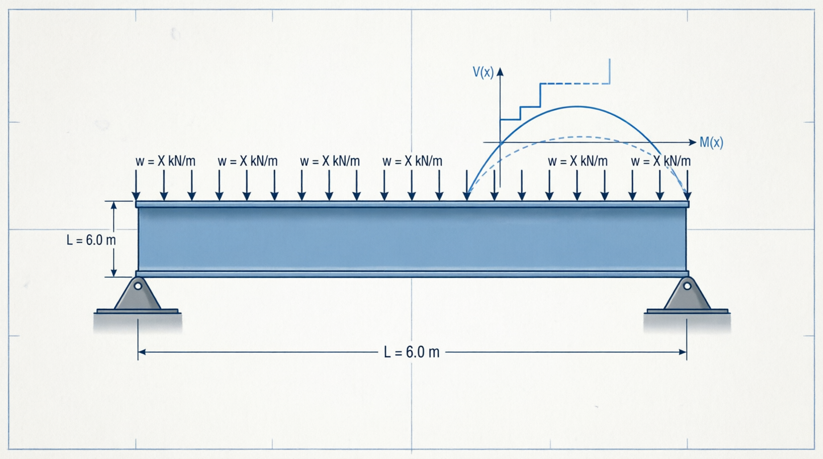
When a load is applied to a beam, it develops internal bending moment (M) and shear force (V). Bending moment causes flexural stress and deflection. Shear force causes shear stress. The maximum bending moment and shear force depend on support type and loading condition. Engineers use shear and moment diagrams to identify critical sections requiring stronger sections or reinforcement.
Span L = 6 m, Point Load P = 20 kN
Reaction at each support: R = P/2 = 10 kN
Maximum Bending Moment (at center): M = PL/4 = 20 × 6 / 4 = 30 kN·m
Maximum Shear Force: V = P/2 = 10 kN
Section Properties and I-Beams
The resistance of a beam to bending is determined by its section modulus (Z = I/c) and moment of inertia (I). Larger sections with material distributed away from the neutral axis (like I-beams and box sections) are more efficient than solid sections. Standard I-beam sizes (150×75, 200×100, 300×150, etc.) are commonly used in construction. Proper section selection ensures adequate strength and limits deflection.
Material Properties and Stress
| Material | Yield Strength | Young’s Modulus (E) | Typical Use |
|---|---|---|---|
| Steel (250 MPa) | 250 MPa | 200 GPa | General structural steel |
| Steel (350 MPa) | 350 MPa | 200 GPa | Higher strength applications |
| Steel (450 MPa) | 450 MPa | 200 GPa | High-strength structural |
| Concrete (M30) | 30 MPa | 32.5 GPa | RCC beams, slabs |
| Wood | 8-20 MPa | 10-15 GPa | Timber structures |
Stress Distribution in Bending
When a beam bends, the top fibers compress while bottom fibers tension (or vice versa). Stress varies linearly from neutral axis: maximum at extreme fibers, zero at neutral axis. Bending stress is calculated as: σ = M/Z (where M is bending moment, Z is section modulus). Maximum bending stress must not exceed allowable stress for the material: σ_max ≤ σ_allowable (= yield strength / safety factor).
Frequently Asked Questions
What is the difference between bending moment and shear force?
Shear force is the internal force perpendicular to the beam axis that resists sliding. Bending moment is the internal moment that resists rotation and causes flexural bending. Both vary along the beam length and are shown in shear and moment diagrams.
How do I reduce beam deflection?
Use a larger section (increased I), reduce span length, use stiffer material (higher E), reduce load, or use prestressing. The most cost-effective approach depends on the specific situation.
Why are I-beams better than solid sections?
I-beams have material concentrated at top and bottom flanges, maximizing moment of inertia for a given weight. This makes them very efficient at resisting bending while minimizing weight and cost compared to solid sections.
What is section modulus?
Section modulus (Z = I/c) is the ratio of moment of inertia to distance from neutral axis. It directly relates bending moment to maximum stress: σ = M/Z. Larger section modulus resists higher moments without excessive stress.
How do I check if a beam is adequate?
Calculate maximum bending moment and deflection for applied loads. Compare with allowable moment capacity (Z × σ_allowable) and allowable deflection (span/240 to span/360). If actual ≤ allowable, beam is adequate.
What is the neutral axis?
The neutral axis is the line through the beam where stress and strain are zero during bending. For symmetric sections like I-beams, it’s at the geometric center. During bending, material above compresses, material below tensions.
Disclaimer: This beam calculator provides estimates for preliminary design. Actual beam design requires detailed structural analysis, consideration of safety factors, dynamic loads, temperature effects, and compliance with building codes and design standards. Always consult with a professional structural engineer for final design and critical applications.