Bridge Expansion & Contraction Calculator
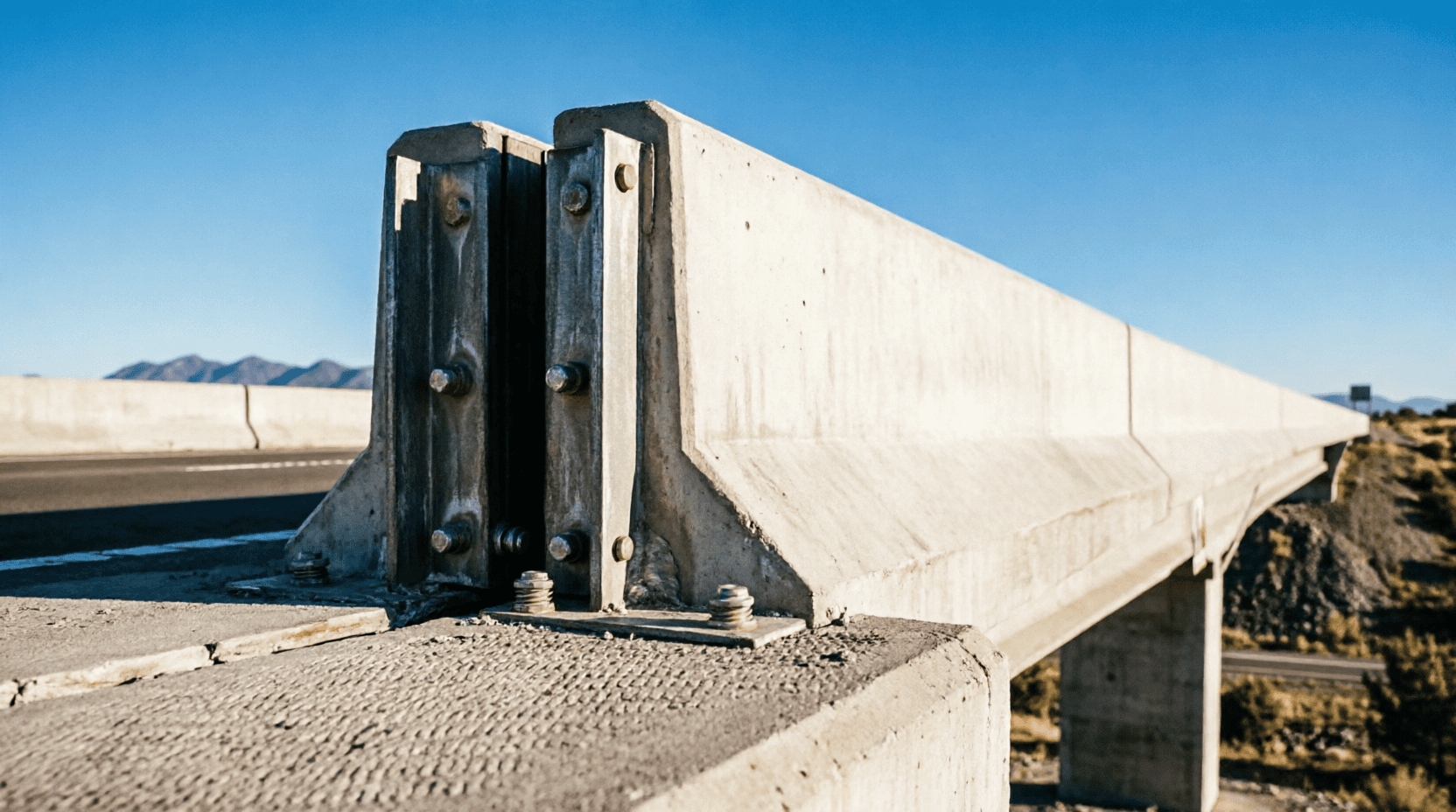
Bridges expand and contract due to temperature changes, concrete shrinkage, creep, and live loads. Failing to account for this thermal movement can lead to severe structural damage, including deck buckling, bearing failure, and cracked abutments. This Bridge Expansion and Contraction Calculator helps civil engineers and designers calculate the total thermal movement of a bridge deck and determine the required width for expansion joints.
Bridge Expansion & Contraction Calculator
Enter the bridge parameters below. The calculator uses the standard linear thermal expansion formula: ΔL = α × L × ΔT.
| Bridge Deck Material | Span Length (L) Enter length in meters (m) |
| Maximum Design Temperature (T_max) Highest expected ambient temperature (°C) | Minimum Design Temperature (T_min) Lowest expected ambient temperature (°C) |
| Temperature at Time of Installation / Closure (T_install) (Optional) Leave blank to calculate total range only. Used to determine max expansion vs max contraction from the fixed point. | |
| Safety / Design Margin (%) | Number of Expansion Joints Movement is divided equally if joints are at both ends |
Coefficients of Thermal Expansion (α)
The coefficient of thermal expansion (α) defines how much a material expands or contracts per degree of temperature change. Values below are standard design values used in civil engineering (per AASHTO and Eurocode guidelines):
| Material | α (per °C) | α (per °F) | Typical Use in Bridges |
|---|---|---|---|
| Reinforced Concrete | 10.0 × 10⁻⁶ | 5.5 × 10⁻⁶ | Standard concrete decks, abutments, piers |
| Prestressed Concrete | 10.8 × 10⁻⁶ | 6.0 × 10⁻⁶ | Pre-tensioned and post-tensioned girders |
| Structural Steel | 12.0 × 10⁻⁶ | 6.7 × 10⁻⁶ | Steel girders, orthotropic decks, trusses |
| Composite (Steel + Concrete) | 11.0 × 10⁻⁶ | 6.1 × 10⁻⁶ | Composite beam bridges |
| Aluminum | 23.0 × 10⁻⁶ | 12.8 × 10⁻⁶ | Specialty pedestrian bridges, railings |
| Masonry / Stone | 5.0 × 10⁻⁶ | 2.8 × 10⁻⁶ | Historic arch bridges, stone abutments |
| Timber | 3.0 to 5.0 × 10⁻⁶ | 1.7 to 2.8 × 10⁻⁶ | Wooden pedestrian bridges (along the grain) |
Design Guidelines for Expansion Joints
Properly sizing and placing expansion joints is critical for bridge longevity. Follow these standard engineering practices:
1. Calculating Total Movement
Where:
• ΔL = Change in length (mm)
• α = Coefficient of thermal expansion (/°C)
• L = Length of the bridge span (mm)
• ΔT = Temperature range (T_max – T_min) in °C
2. Applying Safety Margins
Never size an expansion joint to the exact theoretical movement. Always include a safety margin to account for:
- Construction tolerances and installation errors
- Concrete creep and shrinkage (adds to contraction)
- Live load deflections (shortens the span slightly under heavy traffic)
- Unexpected extreme weather events
Standard Practice: Add a minimum of 20% to the calculated theoretical movement. For bridges in extreme climates or with long spans, use 25%.
3. Joint Placement Strategies
| Bridge Type | Recommended Joint Placement | Notes |
|---|---|---|
| Simply Supported Span | One fixed bearing, one expansion bearing | All movement occurs at the expansion end. Joint must accommodate 100% of ΔL. |
| Continuous Multi-Span | Joints at both abutments only | Movement is split. Each abutment joint accommodates ~50% of total ΔL (if fixed point is in the middle). |
| Integral Abutment Bridges | No expansion joints (fully integral) | Thermal movement is absorbed by the flexible piling. Limited to shorter spans (typically < 60m total). |
Frequently Asked Questions
What is the difference between expansion and contraction in bridges?
Expansion occurs when the bridge deck heats up (summer, midday sun), causing the material to lengthen. Contraction occurs when the deck cools down (winter, night), causing it to shorten. Both movements must be accommodated by bearings and expansion joints to prevent structural stress.
What happens if a bridge has no expansion joints?
If thermal movement is restrained, massive compressive or tensile forces build up in the deck. In summer, the bridge can buckle upwards (thermal buckling). In winter, the concrete can crack or pull away from the abutments. This is why even small bridges require some form of movement accommodation.
Does concrete shrinkage affect the calculation?
Yes. Concrete undergoes long-term shrinkage as it cures and dries, which acts similarly to thermal contraction. For long-term design, engineers often add an equivalent “shrinkage temperature drop” (typically 10°C to 20°C) to the minimum design temperature when calculating total contraction movement.
What is “Bridge Contraction Scour”? (Hydraulic vs. Thermal)
Note: This calculator focuses on thermal expansion/contraction of the bridge deck. In hydraulic engineering, “contraction scour” refers to the erosion of the riverbed caused when a bridge narrows (contracts) the waterway, increasing water velocity. If you need to calculate hydraulic scour, you must use specialized hydraulic formulas (like the Laursen-Thomas equation) based on flow rate, channel width, and soil type.
How often should expansion joints be inspected?
Expansion joints should be inspected at least twice a year (spring and autumn) and after any major seismic event or extreme weather. Look for: debris blockage, sealant failure, rusted steel components, and uneven movement between the deck and abutment.
What is the maximum span length before multiple joints are needed?
Standard finger or strip seal joints can typically accommodate up to 40-80 mm of movement. For longer spans requiring more movement, modular expansion joints (which can handle 100mm to 1000mm+ of movement) are used. The decision depends on the total calculated ΔL, not just the span length.
Understanding Bridge Thermal Movement
All materials expand when heated and contract when cooled. For a 30-meter concrete bridge in a climate with a 50°C temperature range, the deck will change length by approximately 15 mm. While 15 mm seems small, if this movement is restrained, it generates thousands of kilonewtons of force—enough to crush concrete abutments or buckle steel girders.
Proper bridge design requires a “fixed point” (usually a fixed bearing on one pier) from which all movement radiates. Expansion joints and sliding bearings are placed at strategic locations to allow the deck to move freely without inducing stress into the substructure.
Other Factors Affecting Bridge Length
While temperature is the primary driver of daily and seasonal movement, engineers must also consider:
- Concrete Shrinkage: Occurs over the first few years after casting, permanently shortening the deck.
- Creep: Long-term deformation under sustained load (like the weight of the deck itself), which slightly shortens the span.
- Live Load Deflection: Heavy traffic causes the bridge to bend slightly, effectively shortening the horizontal distance between supports.
- Seismic Movement: Earthquakes require additional joint width to prevent the deck from unseating from its bearings during ground shaking.
About This Calculator
This Bridge Expansion and Contraction Calculator computes the linear thermal movement of a bridge deck based on material properties, span length, and temperature range. It includes options for installation temperature and safety margins to help engineers size expansion joints correctly. All calculations are for preliminary design and estimation purposes. Final bridge design must comply with local codes (e.g., AASHTO LRFD, Eurocode, or local Ministry of Works standards) and be verified by a licensed Professional Engineer (PE).